This document presents a technical introduction to MeerKAT, including basic characteristics of the correlator, antennas and array.
Contents
Key specifications
Table 1 provides the specification for the key MeerKAT components. Note that SARAO typically guarantees a minimum of 58 antennas during normal operations. Sensitivity calculations assume 58 antennas. Typical array availability is around 60-62 antennas.
All antennas are equipped with dual (linearly) polarised S-band, L-band and UHF-band receivers. Note that the digitised bandwidth of the L- and UHF-band receivers is larger than the RF bandwidth. Gain stability, sensitivity and other metrics are not guaranteed outside of the frequency ranges listed in Table 1 below. The S-band receiver has a wider RF bandwidth than can be instantaneously digitized, and is broken down into five sub-bands.
Table 1: Key MeerKAT specifications.
Number of antennas | 64 (offset Gregorian) |
Dish diameter (nominal) | 13.5 m |
Minimum baseline | 29 m |
Maximum baseline | 7700 m |
Array phase centre | 30° 42’ 39.8” South, 21° 26’ 38.0” East, 1086.6 m Elevation |
Frequency range (UHF) | 580 - 1015 MHz [544 to 1088 MHz digitised] |
Frequency range (L-band) | 900 - 1670 MHz [856 to 1712 MHz digitised] |
Frequency ranges (S-band) | S0: 1750 - 2625 MHz S1: 1968 - 2843 MHz S2: 2187 - 3062 MHz S3: 2406 - 3281 MHz S4: 2625 - 3500 MHz |
Correlator-beamformer capabilities
The MeerKAT correlator is of an FX type, i.e. first a Fourier transform (F) to frequency is performed, followed by cross-correlation (X). The correlator architecture makes it fully reconfigurable to support different science needs. More information on the correlator-beamformer can be found in the following article: https://www.spiedigitallibrary.org/journals/Journal-of-Astronomical-Telescopes-Instruments-and-Systems/volume-8/issue-01/011006/MeerKAT-correlator-beamformer--a-real-time-processing-back-end/10.1117/1.JATIS.8.1.011006.full?SSO=1
Table 2 lists the imaging modes currently in use for science observations. Data are always recorded in full polarisation, i.e. XX, XY, YX and YY correlations are provided. Auto-correlations are also recorded.
Channelisation
Table 2: Correlator channelisation modes.
Mode | Channels | L-band channel width | UHF-band channel width | S-band channel width |
|---|---|---|---|---|
Wideband coarse | 4096 (4k) | 208.984 kHz | 132.812 kHz | 213.623 kHz |
Wideband fine | 32768 (32k) | 26.123 kHz | 16.602 kHz | 26.703 kHz |
Narrowband extended (107 MHz bandwidth) * | 32768 (32k) | 3.3 kHz | - | |
Narrowband extended (54 MHz bandwidth)* | 32768 (32k) | 1.633 kHz | - |
*The ‘zoom’ or narrowband modes run in parallel with the wideband coarse (4k) mode i.e. you will receive two datasets, enabling continuum as well as spectral line science. We do not support 32k wideband in parallel with a 32k narrowband recording mode.
The wideband coarse (4k) mode is well characterised and a number of papers, including 155 hours integration on the so-called DEEP2 field (Mauch et al. 2020), have been published. This mode has also been used to demonstrate fast survey speed using many short “snapshot” observations.
Please note that no Doppler tracking corrections are done, i.e. the rest frame of MeerKAT data is topocentric.
A more detailed discussion of the narrowband modes can be found here. Note that currently only L-band observations are supported in this mode.
Visibility integration times
The recommended visibility integration period for imaging is 8 s. This would meet the needs of most users while keeping datasets to a manageable size. However, there are cases when shorter integration times may be desired, depending on the extent and nature of the field to be imaged. Supported integration periods are 2, 4 and 8 s. It has been shown that time-smearing at 8 s is not a significant consideration for MeerKAT. Details of relevant simulations and analysis can be found in the MeerKAT time smearing simulation report.
Data rates
With up to 2016 baselines and 4 polarisation products per baseline, plus autocorrelation products, MeerKAT data volumes are not insignificant (see Table 3, or make use of the disk space calculator). Users will also need extra disk space for reductions and imaging. Note that if doing data reduction using CASA, the measurement sets will be at least three times the size of the original visibility data once calibration starts. Options do exist to download a subset of frequencies from the archive, which is particularly useful for spectral line users. Users may wish to first inspect the SDP pipeline products before downloading visibilities.
Table 3: Expected recorded data rates for different correlator channelisation modes, and integration periods. Note that it is not possible to record 32k mode data at 2s.
Visibilities (TB per hour) (2 pols, 4 pols) | |||
Visibility integration period | 2 s | 4 s | 8 s |
4k mode | 0.5 ,1 | 0.2, 0.5 | 0.1, 0.2 |
32k mode | - | 1.9, 3.9 | 1, 1.9 |
Array layout
The MeerKAT array has a ‘core heavy’ configuration as follows:
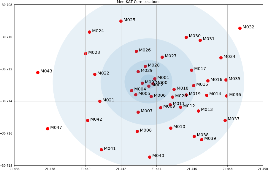
A dense inner component containing 70% of the dishes. These are distributed in a two-dimensional fashion with a Gaussian uv distribution with a dispersion of 300 m, a shortest baseline of 29 m and a longest baseline of 1 km (Figure 1).
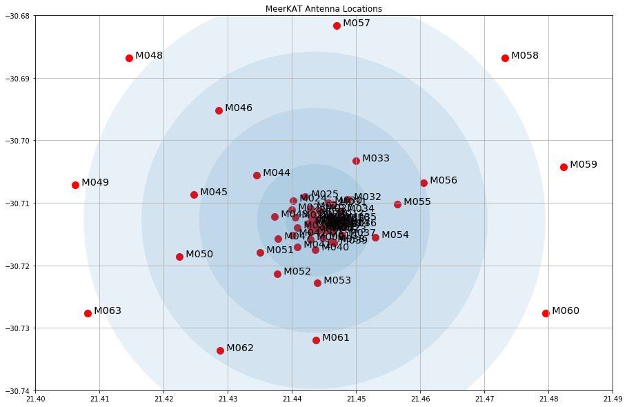
An outer component containing 30% of the dishes. These are also distributed in a 2D Gaussian uv-distribution, with a dispersion of 2500 m and a longest baseline of 7.7 km (Figure 2).
The list of antenna positions can be found in this spreadsheet. Note that the array layout is optimised for southern sources and imaging performance may be degraded for sources north of the equator.
Interactive Google map of antenna layout.
uv coverage
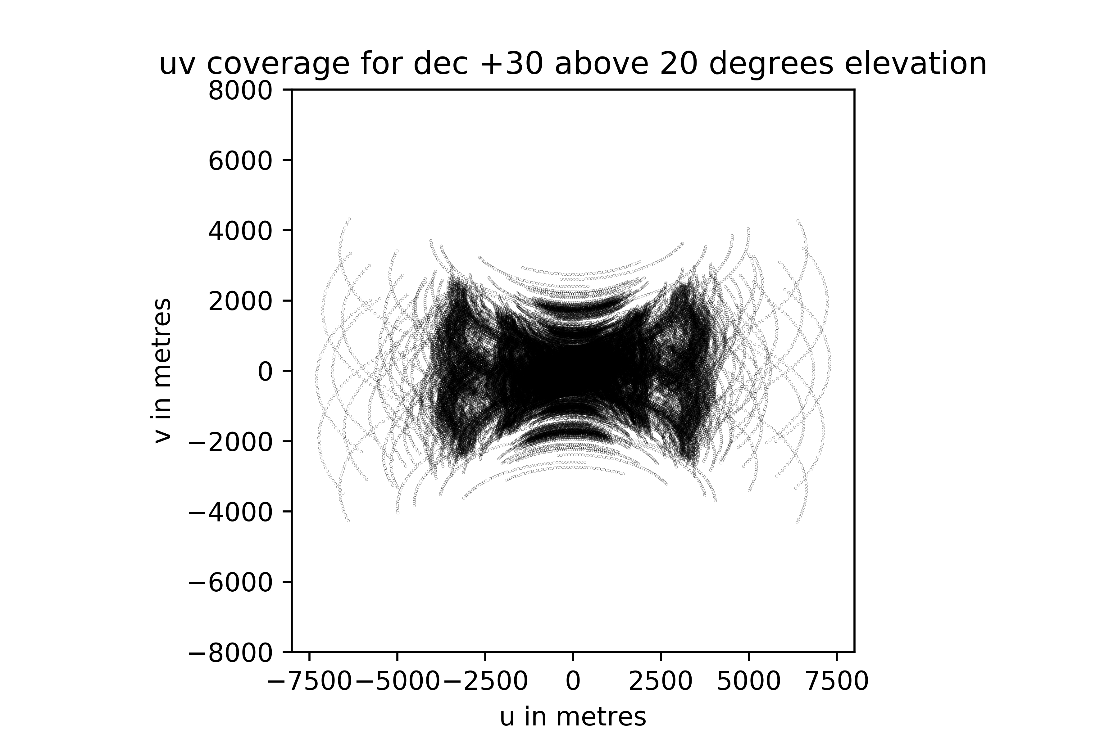
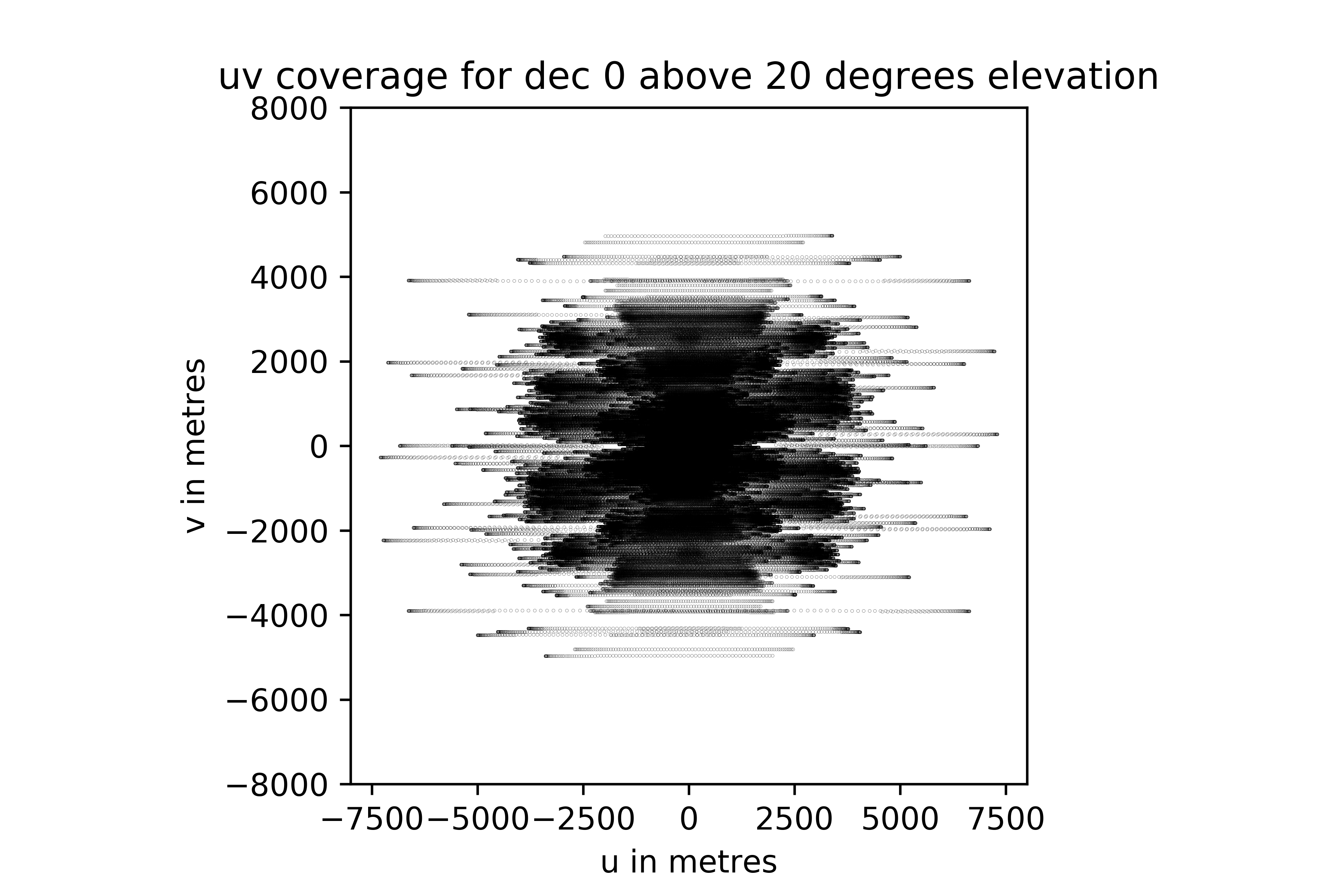
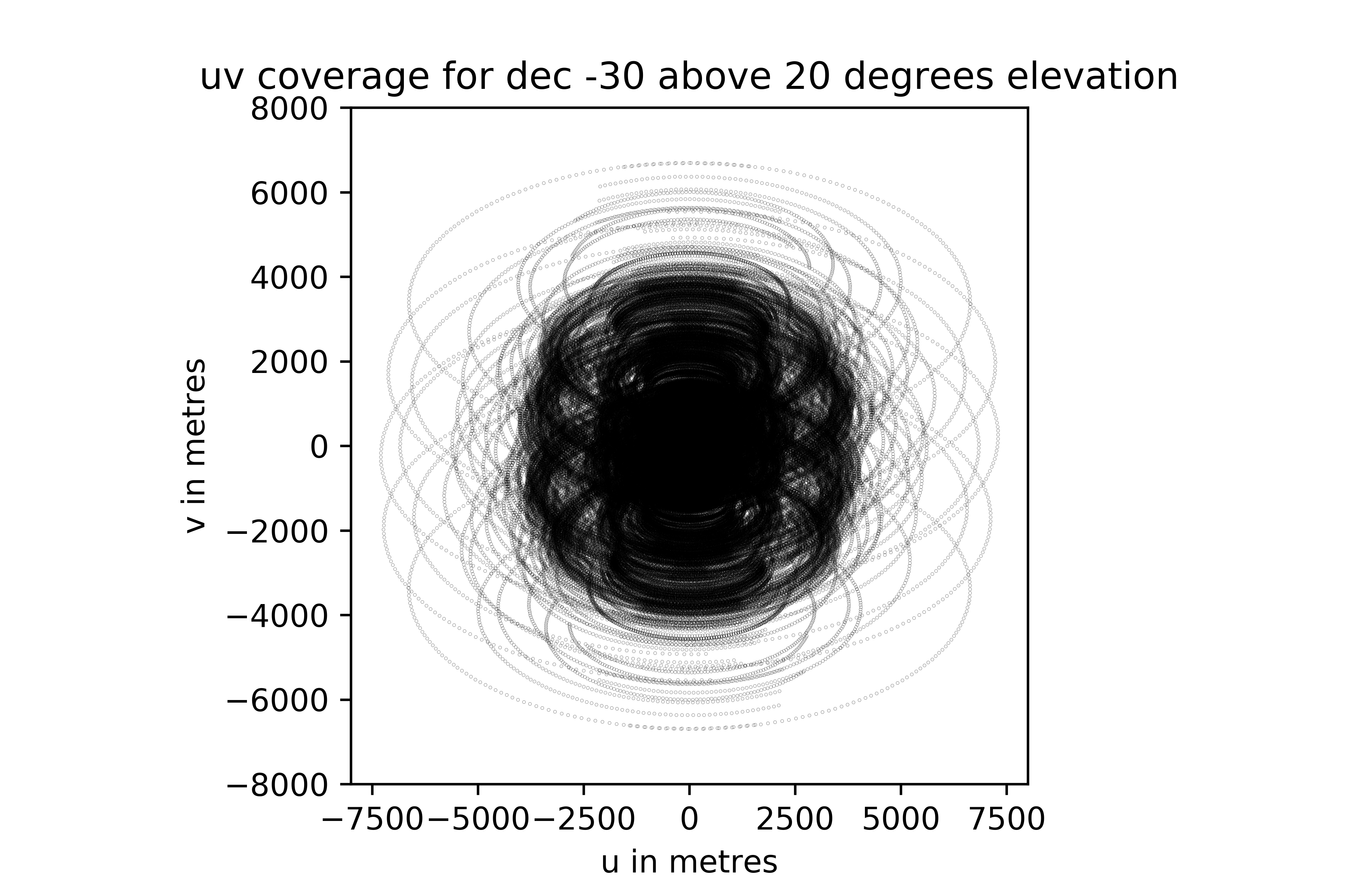
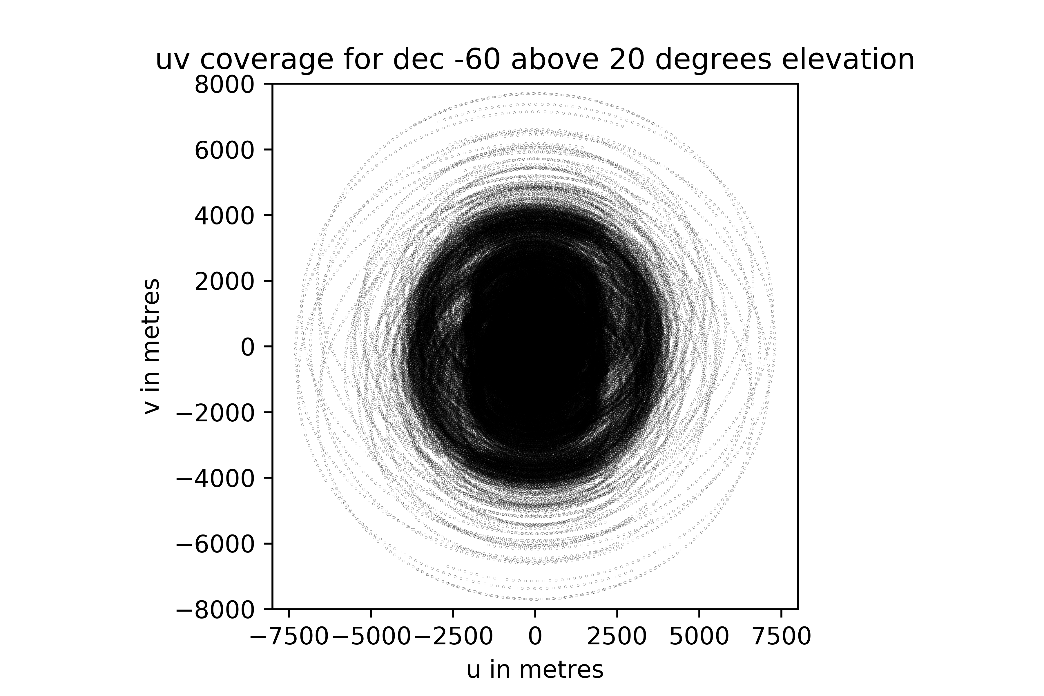
In Figure 3 we show examples of the expected uv coverage at various declinations, for full tracks above a 20° horizon limit. A simplified uv coverage simulator is available here. Instructions on how to do full simulations in CASA and MeqTrees of your target field can be found here.
Figure 3: uv coverage for a selected range of declinations, assuming a full track above 20° elevation. These plots are frequency-independent, and can be scaled by dividing by your wavelength of interest.
Northern declination limit
The antennas have an elevation limit of 15 degrees, thus sources sources north of ~ + 42 dec cannot be observed at all. The plot below shows the time sources are above the antenna horizon limits for all declinations.
Antenna specifications
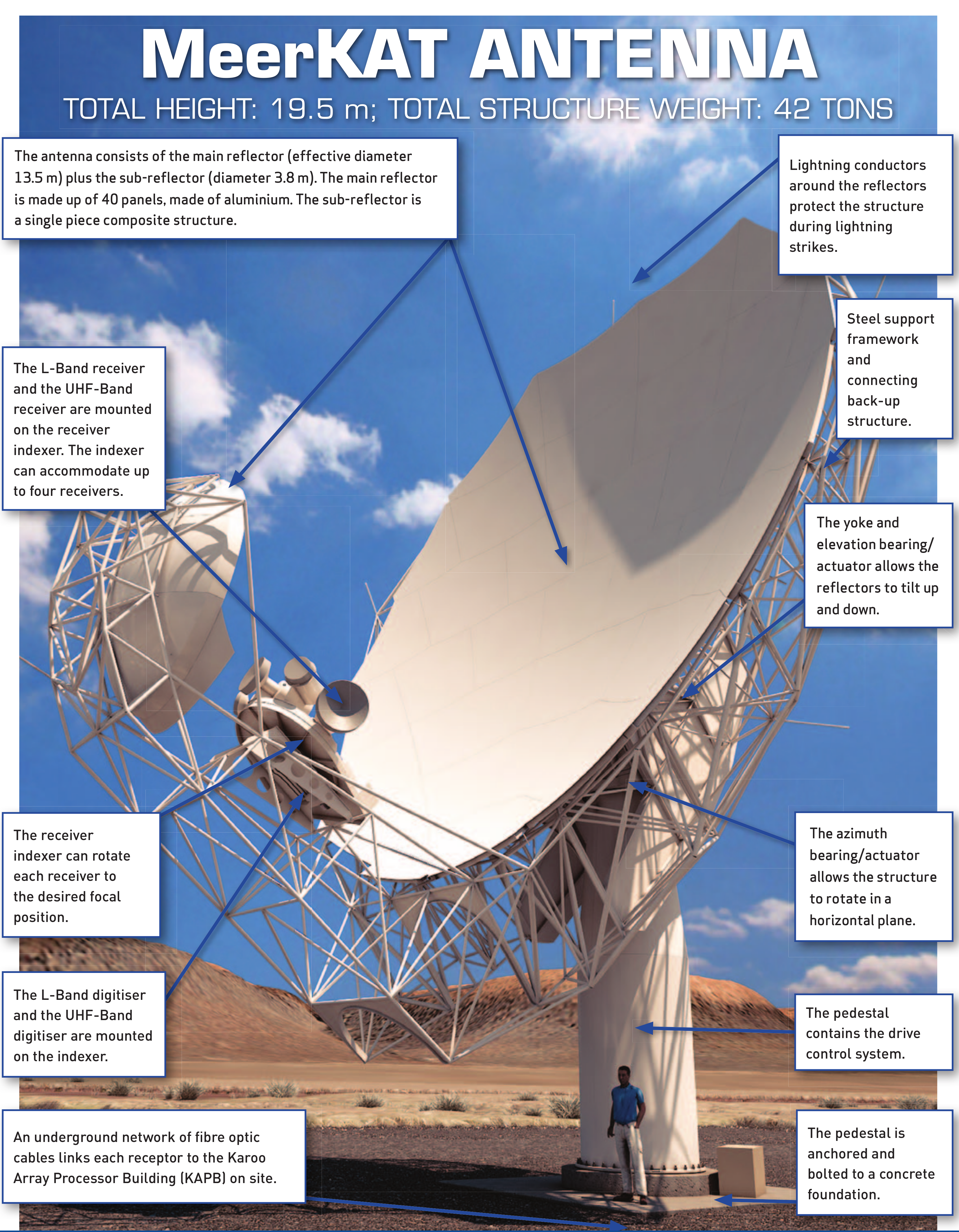
The MeerKAT dishes are 13.5 m in diameter (nominal; the effective equivalent diameter is nearly 14 m) and are of an offset Gregorian design (Figure 4). The antenna positioner is of an azimuth-elevation drive design. Key performance parameters are given in Table 4.
Table 4: Key specifications for MeerKAT antenna positioners.
elevation slew speed | 1 °/s |
azimuth slew speed | 2 °/s |
settling time after position step of 0.5° | 2.7 s |
settling time after slewing (long slew >7°) | 8 s |
elevation pointing range | 15° to 89° |
blind pointing accuracy | ~ 0.6 arcmin |
The Solar zone of avoidance
The effect of Solar radiation on a radio telescope observation can be severe when the Sun is close to the target of the observation. The minimum separation angle is determined by the amplitude of the Solar contribution to the system temperature. Although this ensures that the Solar radiation has not impacted the telescope sensitivity there still may be complications in the data analysis. The observatory scheduling staff work to ensure that a source is never observed within the minimum Solar angular separation.
Band | Minimum Solar angular separation[degrees] |
|---|---|
UHF-band | 15 |
L-band | 10 |
S0-band | 9 |
S4-band | 6 |
The minimum Solar angular separation was determined in the report Measuring the Solar zone of avoidance for the MeerKAT antennas.
Shadowing
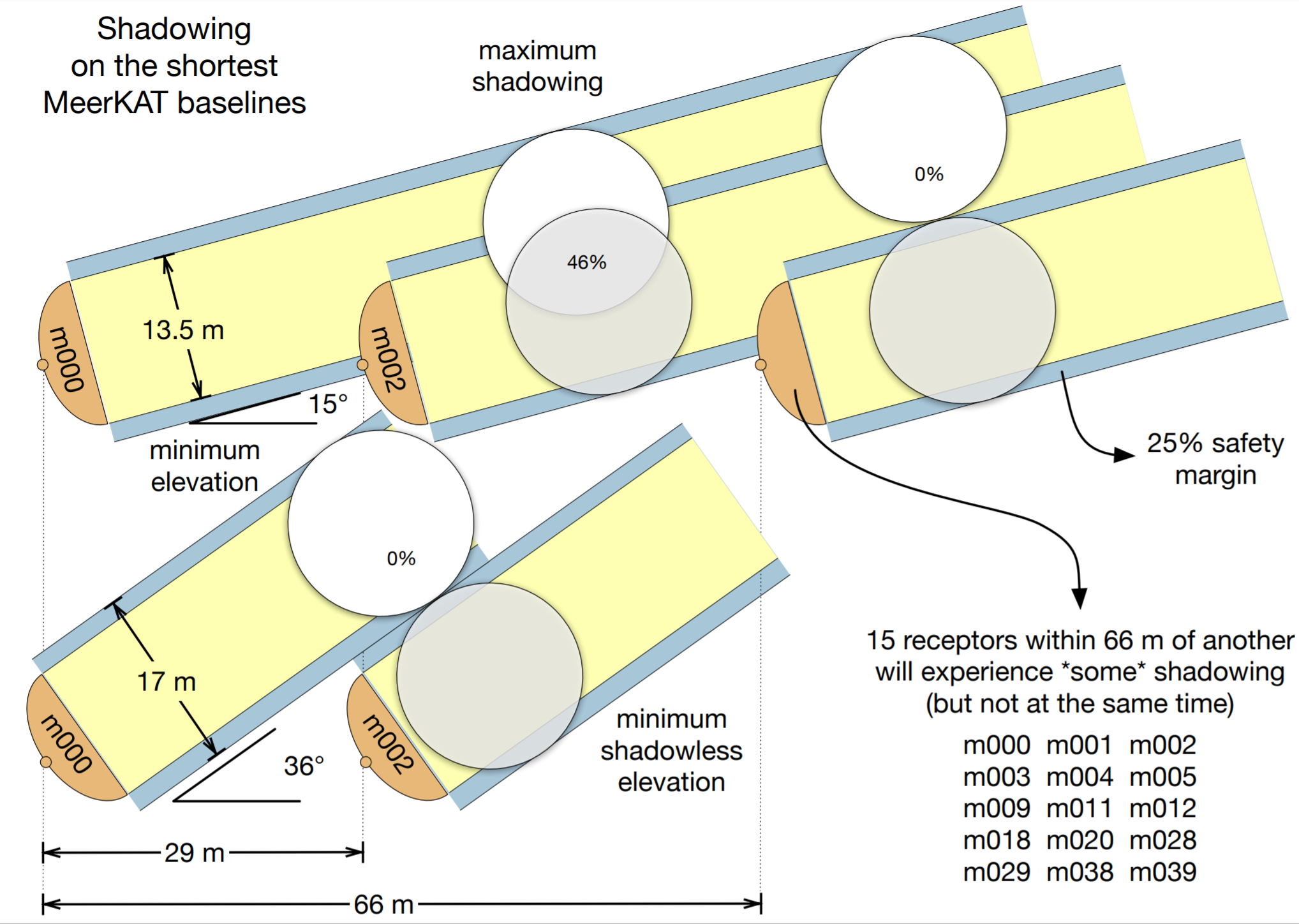
Despite the closely packed core, shadowing is generally minimal since antennas have a 15 deg minimum elevation limit. There are 15 antennas within 66 m of each other that can experience shadowing some of the time, but since the sight-lines are all different they won't all be affected at the same time.
System temperature
For the purposes of determining the sensitivity of proposed observations, we consider the system temperature Tsys to be the total temperature of all factors that influence the signal path. This can be broken down into four components,
Tsys = Tsky (ra,dec,ν)+ Tspill (el,ν)+ Tatm(el,ν) + Trec
For the system temperature presented below we assume that the telescope is pointed away from hotter areas in the sky at a representative 'cold sky'. The mean sky temperature at b < -40° is approximated by the function Tsky= 2.725 + 1.6(ν/GHz)-2.75 which is used as the representative cold sky. The receiver temperature term Trec contains all the constant contributions to system performance such as receiver, correlator, antenna temperature etc.
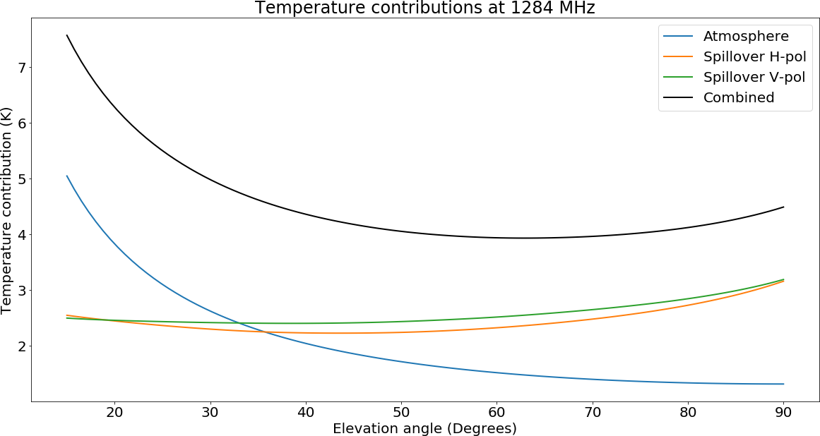
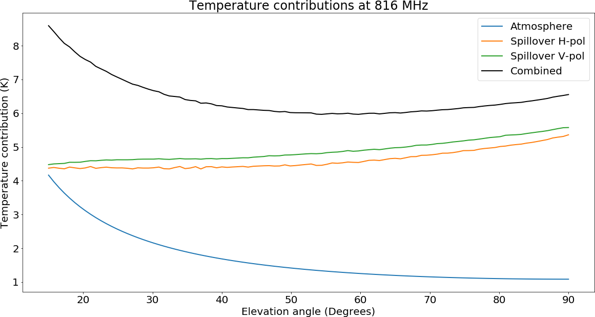
The spillover and atmospheric temperature are calculated from simulations. The contributions of the two components are shown below (Figures 6 and 8) at the central frequency of the band. Users who do not need full tracks may wish to avoid lower elevations in order to minimise this contribution. Note that observations of sources far to the north will be at a lower elevation and subject to higher system temperature due to increased Tatm and thus have reduced sensitivity. In the figures below we use an elevation of 55° for the calculation of system temperature.
Figures 7 and 9 show the mean measured MeerKAT system temperature over aperture efficiency (Tsys/η) across the full array.
L-band
UHF band
System Equivalent Flux Density (SEFD)
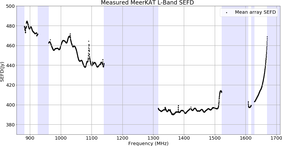
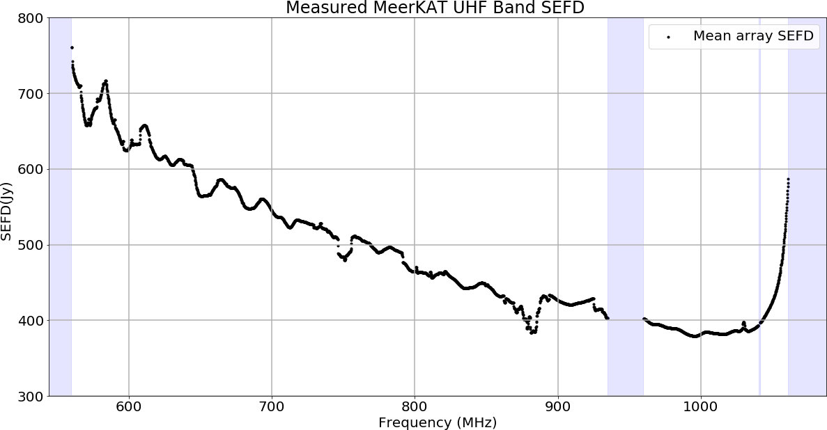
The SEFDs presented in Figures 10 and 11 below correspond to the Tsys measurements above.
L-band
UHF band
S-Band
The mean SEFD per antenna is given in Figure 1 below.
Due to logistical issues, availability of the S-band receivers is somewhat lower than that of UHF and L-bands. Users should assume a lower limit of 56 antennas for sensitivity estimates.
Primary beam characteristics
More details on the primary beam, based on holography measurements, can be found on this page.
Some of the following results are drawn from Mauch et al. (2020).
The 13.5 m diameter MeerKAT dishes have a Stokes I primary beam attenuation pattern that is well matched by the attenuation pattern resulting from cosine-tapered field (or cosine-squared power) illumination (Condon & Ransom 2016):
Figure 14 shows that the attenuation pattern of the cosine illumination taper is a good match out to a radius of 2.5° and matches best the main lobe of the primary beam out to 1.2°. This pattern has the practical advantage of expressing ab(ρ/θb) as an elementary function that is quick to compute. It is therefore most suitable for making simple primary beam corrections in the image plane (e.g. for mosaicing).
We have measured the primary attenuation pattern of the main lobe by making a series of snapshot images offset by 10', 20', 30', 40', and 50' to the north, south, east, and west of the calibration source J1939-6342. The flux density and position of the source were measured in each image by fitting an elliptical Gaussian to the source.
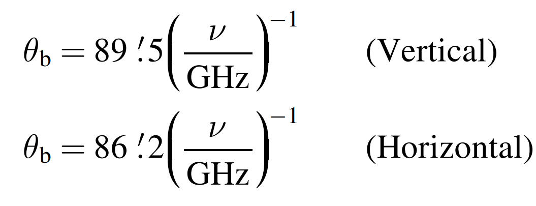
Figure 15 shows fits of the attenuation pattern of cosine illumination taper to the flux densities measured from our J1939-6342 observations. During the fitting, we inserted the mean pointing offset Δ as a free parameter, replacing (ρ/θb) in the above equation by [(ρ − Δ)/ θb]. The horizontal and vertical fits of the attenuation power pattern are an excellent match to the data for all |ρ|<50’. Note that the primary-beam pattern is slightly elliptical; its vertical θb is larger than its horizontal θb.
We used wideband images of J1939-6342 covering the frequency range 886–1682 MHz centred on ν = 1.28 GHz to fit the primary beam in Figure 12. We have further split the band into 14 narrow sub-bands and repeated the beam fitting described above for each. Figure 13 shows that the product θbν varies by <±3% across the band for both the vertical and horizontal cuts through the beam. The best L-band approximations with fixed θbν are:
Flux density measurements past the half-power point may be in error by 2-3%. However, for many users, this simple approximation is sufficient, and an example of how to apply this beam model is shown below.
Defining the simplified primary beam model in CASA
def beam (offsetx, offsety, freq) :
   """ freq in MHz
  offsetx, offsety in degrees """
  FWHM = np.sqrt(89.5∗86.2)/60.∗(1e3/freq)
  theta = np.sqrt(offsetx∗∗2 + offsety∗∗2)
  a = (np.cos(1.189∗np.pi∗(theta/FWHM))/(1−4∗(1.189∗(theta/FWHM))∗∗2))∗∗2
  return a

MEERKAT_PB = vp.setpbnumeric(
  telescope = 'OTHER',
  othertelescope = 'MeerKAT',
  dopb = True,
  vect = beam(np.linspace(0,3.0, 1000), 0, 1400.0),
  maxrad = '3.0 deg',
  reffreq = '1.4 GHz',
  isthispb = 'PB',
  dosquint = False)
vp.saveastable('MEERKAT_PB.tab' )
.png?version=1&modificationDate=1680774668892&cacheVersion=1&api=v2)
.png?version=3&modificationDate=1593446587627&cacheVersion=1&api=v2)
.png?version=2&modificationDate=1593446445385&cacheVersion=1&api=v2)


Add Comment